2D Rendering - 6 - Textured Quads
 Download the source code for this post
Welcome back, me old muckers. The good news is, these tutorials will start ramping up to the more exciting stuff now that we’ve more or less got triangles out of the way.
In this post I just want to touch on how to use shaders to render textures over the quad that we created in my previous post.
You don’t strictly need to know this when working with libGDX (at least for 2d anyway), as libGDX includes very similar sprite functionality to XNA. However, knowing at least the basics of what is going on under the hood of libGDX will give you more power at your fingertips, should you need it later on.
So, remove those XNA blinkers and read on.
Texture Coordinates
Just when you got used to Normalised Device Coordinates (NDC), I’m pleased to inform you that textures have there own different co-ordinate system, as shown below.
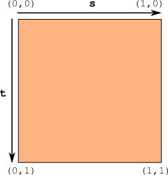 .
.
The origin sits at the top-left hand corner, where the s axis extends to the right and the t axis extends downwards. What’s all this s and t nonsense? Well, you can think of it as x and y. When working with texture coordinates, they are referred to as s and t, or, just to confuse the issue further, u and v. In short, you can think of it as: (x,y) == (s,t) == (u,v).
libGDX’s texture coordinate system differs slightly from OpenGL’s, which has the origin at the botom-left hand corner. I can only assume that libGDX supports the alternate coordinate system for our convenience, and is flipping the image on the t axis behind the scenes. Fax me if I am wrong…
Once again, good old normalisation comes into play, thus allowing us to work with any texture, regardless of its dimensions. However, this time the range is 0…1, as with normalised colours.
Mapping texture coordinates to vertices
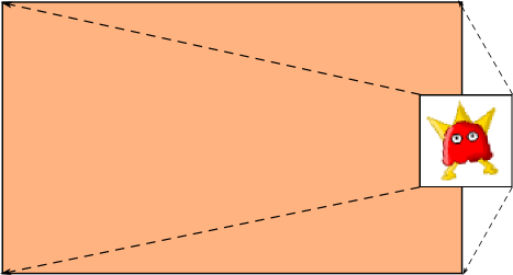
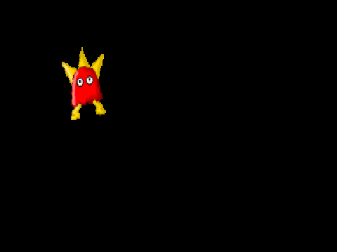
Allow me to introduce Krazy Bob.

He is a 64 x 64 texture, stored as a png file. Rumour has it that OpenGL ES 2 supports non power of two (NPOT) sized images, but I’ve read about certain restrictions, so I’ve decided to stick with power of two sizes.
If you unsure what power of two sized means, then I’ll use Krazy Bob as an example. 2^6 = 64 and Bob’s size is 64 x 64, so he’s a power of two sized texture. Nice one Bob.
What we are going to do is take Bob and stretch him across the face of the quad we rendered in my previous post, as shown below.
To do this, we need to encode a different type of data into our Mesh, to accompany the vertices which make up our quad. In the Mesh constructor, we describe what we are encoding, in the same way we described that we were encoding colour data along with each vertex in a previous post.
mesh = new Mesh(true, 4, 0,
        new VertexAttribute(Usage.Position, 2, "a_position"),
        new VertexAttribute(Usage.TextureCoordinates, 2, "a_texCoord")); // <<<<<====
The highlighted line shows the new type of data that we are encoding, and indicates that we will be sending two coordinates - s and t per datum. We name the attribute a_texCoord, which we will make use of in our vertex shader.
Next we encode the texture coordinates along with each vertex.
float[] vertices = {
	-0.5f, -0.5f,	// quad bottom left
	0.0f, 1.0f, 	// texture bottom left
	0.5f, -0.5f, 	// quad bottom right
	1f, 1.0f, 	// texture bottom right
	-0.5f, 0.5f,	// quad top left
	0.0f, 0.0f, 	// texture top left
	0.5f, 0.5f,     // quad top right
	1.0f, 0.0f      // texture top-right
};
mesh.setVertices(vertices);
If you read the comments in the code above, you will see that we have an interleaved array of vertices and texture coordinates, where we are mapping the texture coordinates for each corner of our texture to a vertex for each corner of our quad, as shown in the image above.
Next we need to make some small adjustments to our shaders.
Vertex Shader
Our new vertex shader is as follows
attribute vec4 a_position;
attribute vec2 a_texCoord;varying vec2 v_texCoord; void main(){
    gl_Position = a_position;
    v_texCoord = a_texCoord; }
a_texCoord receives the texture coordinates that we added to our Mash earlier. v_textCoord is how we are going to pass the texture coordinates to our fragment shader. Note that this variable is of type varying. The last time we used varying is when we had the vertex shader interpolate between the colours of two or more vertices. This time, the varying type is being used to interpolate across the surface of a texture, and it is those interpolated co-ordinates that will be passed to our fragment shader.
To make this clearer, imagine that the vertex shader is bang smack in the middle of our quad. In this case, it needs the texel that is bang smack in the middle of our texture, which is (0.5,0.5). That is the texture co-ordinate that our fragment shader will receive.
If you don’t know what the other parts of this shader are doing, or you don’t know much about interpolation and normalisation, then please understand that there is a dark force at play read my previous tutorials!
Fragment Shader
Our shiny new fragment shader looks as below:
varying vec2 v_texCoord;                               // 1.
uniform sampler2D u_texture;
void main() {
  gl_FragColor = texture2D( u_texture, v_texCoord );   // 4.
}
On line 1, we receive the interpolated texture coordinate, which the vertex shader kindly calculates for us, based on where it currently is between quad vertices.
The uniform u_texture of type sampler2D is how the fragment shader gets a handle on the texture we want it to use. We’ll see how we bind the texture from our Java code a bit further down.
Finally, on line 4, we set OpenGL’s fragment colour to that of the textures colour from the interpolated coordinate, via a glsl function call to texture2D().
texture2D() takes a texture id and a normalised coordinate, and returns a calculated colour for the texel at that coordinate. You’ll see what I mean when I say calculated further down, where I cover filtering.
Loading our texture
To load our texture, we add it to our assets folder (see source repo) and simply load it in as follows:
private void createTexture () {
	texture = new Texture("bob.png");
}
Rendering Krazy Bob
Our rendering code begins by clearing the scene, as usual.
Gdx.gl.glClearColor(0, 0, 0, 1);
Gdx.gl20.glClear(GL20.GL_COLOR_BUFFER_BIT);
Next we tell OpenGL what algorithm to use should it need to stretch of shrink our texture when it covers the quad. This is referred to as filtering in the OpenGL world. In our case, we are stretching it, which is known in the trade as magnification. The process of shrinking the texture is known as minification.
In the call to setFilter(), the first parameter controls minifiation, and the second, magnification.
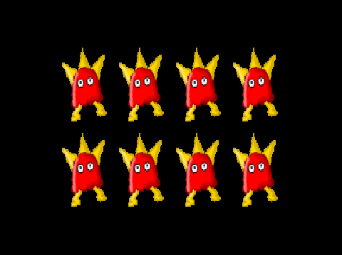
We have chosen an algorithm called Nearest. With Nearest, the pixel colour becomes the color of the nearest texel to the interpolated coordinate computed by the vertex shader. This takes me back to the greatest decade ever, the 80’s, as it produces blocky looking 8-bit style graphics.
texture.setFilter(TextureFilter.Nearest, TextureFilter.Nearest);
Next, we tell OpenGL what texture we want it to use when our shaders are executed.
You can think of OpenGL as a state machine. By that, I mean you set it to some state, then call various API functions, which work based on the current state that it is in. Below is a classic example of this. OpenGL has a finite number of slots which can have textures bound to them. In the code below, we set the state by setting the active texture to GL20.GL_TEXTURE0 and then we bind our texture to OpenGL’s active texture slot.
Gdx.gl20.glActiveTexture(GL20.GL_TEXTURE0);
texture.bind();
Finally, we render the damn thing. The highlighted line below is where we communicate with our shader, to tell it which texture we want it to work with. The zero basically represents the GL20.GL_TEXTURE0, which we bound our texture to.
shader.begin();
shader.setUniformi("u_texture", 0); // <--- Here it be!
mesh.render(shader, GL20.GL_TRIANGLE_STRIP);
shader.end();
Well, all of that sounded like a bit of an ordeal, didn’t it? Well, calm yourselves down and take comfort in the knowledge that when we put all of that together, the code is very short:
Gdx.gl.glClearColor(0, 0, 0, 1);
Gdx.gl20.glClear(GL20.GL_COLOR_BUFFER_BIT);
texture.setFilter(TextureFilter.Nearest, TextureFilter.Nearest);
Gdx.gl20.glActiveTexture(GL20.GL_TEXTURE0);
texture.bind();
shader.begin();
shader.setUniformi("u_texture", 0);
mesh.render(shader, GL20.GL_TRIANGLE_STRIP);
shader.end();
When we execute this code, we see Krazy Blocky Bob, in all of his glory.

More Texture Filtering
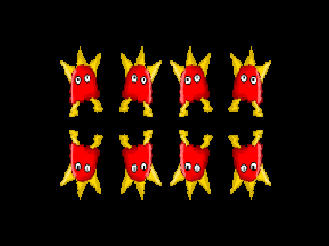
One of the other filtering algorithms that we can use is Bilinear Interpolation. Put simply, the nearest texel (of the interpolated coordinate) is combined with its 4 nearest neighbouring texels. We can switch to this filtering mode by making the code change:
texture.setFilter(TextureFilter.Linear, TextureFilter.Linear);
Krazy Bilinear Bob, now looks as smooth as a baby’s bottom:

Texture Wrapping
You know how earlier I mentioned that texture coordinates are normalised to a value between 0…1? Well, what happens if we pass in values higher or lower than that? Well, OpenGL uses this inconceivable madness to provide some very useful functions.
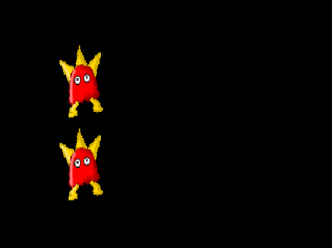
First, lets look at repeating. To do this, I’m going to change the vertex to texel mappings as follows.
float[] vertices = {
	-0.5f, -0.5f,	// quad bottom left
	0.0f, 2.0f, 	// texture bottom left
	0.5f, -0.5f, 	// quad bottom right
	4.0f, 2.0f, 	// texture bottom right
	-0.5f, 0.5f,	// quad top left
	0.0f, 0.0f, 	// texture top left
	0.5f, 0.5f,	// quad top right
	4.0f, 0.0f 	// texture top-right
};
If you look carefully at the texture coordinates, you will see that I am effectively saying that the width is 4 times bigger, and the height 2 times bigger.
Finally, I set the wrap mode for the texture, to tell it to repeat.
texture.setWrap(TextureWrap.Repeat, TextureWrap.Repeat);
Note that setWrap()’s first parameter is used to specify what to do in the s direction, and the second parameter specifies what to do in the t direction.
When we run this, we get 4 x 2 Krazy Bobs. As if one wasn’t enough!
If I make the following change:
texture.setWrap(TextureWrap.MirroredRepeat, TextureWrap.MirroredRepeat);
Note that axes s and t are completely independent of each other, so we could, for instance, repeat non-mirrored vertically and mirrored horizontally if we wanted to.
Now for some clamping.
texture.setWrap(TextureWrap.ClampToEdge, TextureWrap.ClampToEdge);
This time, we are back to a single Krazy Bob, albeit smaller than our initial Krazy blocky Bob. In fact, he is 4 times smaller in width and 2 times smaller in height, which directly correlates to the 4.0 and 2.0 texture coordinates we associated with our vertices.
Finally, I’ll push the boundaries and demonstrate a mixture of techniques on the s and t axes.
texture.setWrap(TextureWrap.ClampToEdge, TextureWrap.Repeat);
Hopefully, you can by now deduce what this will achieve? Otherwise, I have failed in my quest to educate you. Just in case, here we go.
TL;DR

Coming up next…
It’s time to say goodbye to Normalised Device Coordinates (NDC) and do things properly.
JK